LQR 控制器设计

参考 双轮足式机器人分析

连杆质心拟合
1745170081104.png

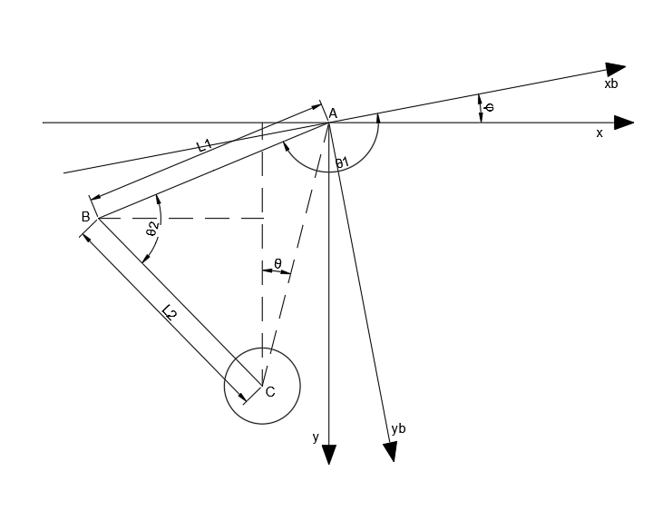
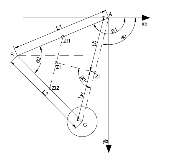
由于在分析和设计控制器的过程中,机器人的腿部连杆需要简化为一个直杆,所以就需要将原来的腿部连杆的转动惯量和质心拟合到虚拟的杆上,如图所示

这里使用机体坐标系,计算可以得到每个杆的坐标位置

Zl1=[l1bcos⁡θ1l1bsin⁡θ1]Zl2=[l1cos⁡θ1+l2bcos⁡(θ2+θ1−180°)l1sin⁡θ1+l2bsin⁡(θ2+θ1−180°)]Z_{l_1}=\begin{bmatrix}l_{1b}\cos\theta_1\\l_{1b}\sin\theta_1\end{bmatrix}\\Z_{l_2}=\begin{bmatrix}l_1\cos\theta_1+l_{2b}\cos(\theta_2+\theta_1-180\degree)\\l_1\sin\theta_1+l_{2b}\sin(\theta_2+\theta_1-180\degree)\end{bmatrix}

计算其组合体的质心位置

m1Zl1+m2Zl2=(m1+m2)Z1m_1Z_{l_1}+m_2Z_{l_2}=(m_1+m_2)Z_1

之后将组合体的质心映射到虚拟杆上,这里直接使用垂足进行映射,是由于点到直线,垂线最短,从而质心映射拟合时产生的误差会最小,联立如下方程求解

(Z1y−ZlyZ1x−Zlx)(Cy−AyCx−Ax)=−1Cy−ZlyCx−Zlx=Cy−AyCx−Ax(\frac{Z_{1y}-Z_{ly}}{Z_{1x}-Z_{lx}})(\frac{C_y-A_y}{C_x-A_x})=-1\\\frac{C_y-Z_{ly}}{C_x-Z_{lx}}=\frac{C_y-A_y}{C_x-A_x}

求解即可得到 ZlZ_l 坐标,根据平行轴定理可以得到变换之后的质心处的转动惯量

Il=I1+m1(Zl−Zl1)T(Zl−Zl1)+I2+m2(Zl−Zl2)T(Zl−Zl2)I_l=I_1+m_1(Z_l-Z_{l_1})^T(Z_l-Z_{l_1})+I_2+m_2(Z_l-Z_{l_2})^T(Z_l-Z_{l_2})

同时也可以计算出所需要的 LwL_w 和 LbL_b

Lw=(Zl−C)T(Zl−C)Lb=(Zl−A)T(Zl−A)L_w=\sqrt{(Z_l-C)^T(Z_l-C)}\\L_b=\sqrt{(Z_l-A)^T(Z_l-A)}

腿部连杆运动学正解

1745158556666.png

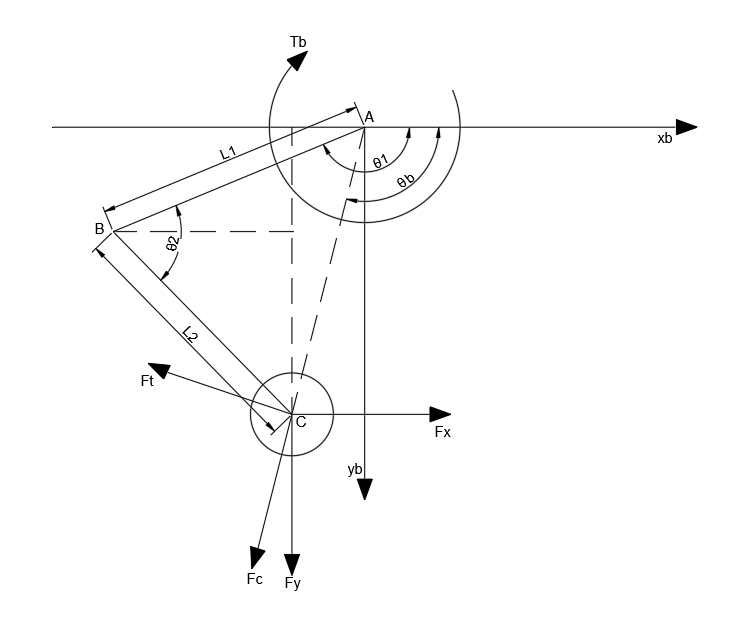
如图所示,首先基于机体坐标系 xb−ybx_b-y_b 来计算各点的坐标,腿长 LL 和腿部摆角角度 θ\theta

Ab=[00]Bb=[l1cos⁡θ1l1sin⁡θ1]Cb=[l1cos⁡θ1+l2cos⁡(θ2+θ1−180°)l1sin⁡θ1+l2sin⁡(θ2+θ1−180°)]A_b=\begin{bmatrix}0\\0\end{bmatrix}\\B_b=\begin{bmatrix}l_1\cos\theta_1\\l_1\sin\theta_1\end{bmatrix}\\C_b=\begin{bmatrix}l_1\cos\theta_1+l_2\cos(\theta_2+\theta_1-180\degree)\\l_1\sin\theta_1+l_2\sin(\theta_2+\theta_1-180\degree)\end{bmatrix}

利用旋转矩阵将坐标点 CbC_b 旋转到坐标系 x−yx-y 上,最终计算出来的 CC 如下

C=[cos⁡φsin⁡φ−sin⁡φcos⁡φ]CbC=\begin{bmatrix}\cos\varphi&\sin\varphi\\-\sin\varphi&\cos\varphi\end{bmatrix}C_b

计算腿长 LL 和腿部摆动角度 θ\theta 如下

L=Cx2+Cy2θ=arctan⁡(−CxCy)L=\sqrt{C_x^2+C_y^2}\\\theta=\arctan(-\frac{C_x}{C_y})

解算得到

L=l12−2cos⁡(θ2)l1l2+l22θ=arctan⁡(l2cos⁡(θ1−φ+θ2)−l1cos⁡(φ−θ1)−l2sin⁡(θ1−φ+θ2)−l1sin⁡(φ−θ1))L=\sqrt{l_1^2-2\cos(\theta_2)l_1l_2+l_2^2}\\\theta=\arctan\Big(\frac{l_2\cos(\theta_1-\varphi+\theta_2)-l_1\cos(\varphi-\theta_1)}{-l_2\sin(\theta_1-\varphi+\theta_2)-l_1\sin(\varphi-\theta_1)}\Big)

在具体使用中还需要得到它们的导数,化简之后得到如下的公式

L˙=l1l2sin⁡(θ2)θ˙2Lθ˙=(l22−l1l2cos⁡(θ2))θ˙2L2−φ˙+θ˙1\dot{L}=\frac{l_1l_2\sin(\theta_2)\dot{\theta}_2}{L}\\\dot{\theta}=\frac{(l_2^2-l_1l_2\cos(\theta_2))\dot{\theta}_2}{L^2}-\dot{\varphi}+\dot{\theta}_1

VMC

1745158591120.png

此处采用机体坐标系即 xb−ybx_b-y_b ,根据上述所计算的 CbC_b 点计算腿长参数和腿部摆动角 θb\theta_b ,如下

Lb=Cbx2+Cby2θb=arctan⁡CbyCbxL_b=\sqrt{C_{bx}^2+C_{by}^2}\\\theta_b=\arctan\frac{C_{by}}{C_{bx}}

计算其对于 θ1\theta_1 和 θ2\theta_2 的雅各比矩阵

[Lbθb]=J[θ1θ2]\begin{bmatrix}L_b\\\theta_b\end{bmatrix}=J\begin{bmatrix}\theta_1\\\theta_2\end{bmatrix}

但是此处求解得到的雅各比矩阵 JJ 十分复杂,所以将极坐标转换为平行坐标来计算

[FxFy]=[cos⁡θb−sin⁡θbLbsin⁡θbcos⁡θbLb][FTb]\begin{bmatrix}F_x\\F_y\end{bmatrix}=\begin{bmatrix}\cos\theta_b&-\frac{\sin\theta_b}{L_b}\\\sin\theta_b&\frac{\cos\theta_b}{L_b}\end{bmatrix}\begin{bmatrix}F\\T_b\end{bmatrix}

可以将 CC 点坐标进行求解雅各比矩阵,得到

[C˙bxC˙by]=[l2sin⁡(θ1+θ2)−l1sin⁡θ1l2sin⁡(θ1+θ2)l1cos⁡θ1−l2cos⁡(θ1+θ2)−l2cos⁡(θ1+θ2)][θ˙1θ˙2]=J[θ˙1θ˙2]\begin{bmatrix}\dot{C}_{bx}\\\dot{C}_{by}\end{bmatrix}=\begin{bmatrix}l_2\sin(\theta_1+\theta_2)-l_1\sin\theta_1&l_2\sin(\theta_1+\theta_2)\\l_1\cos\theta_1-l_2\cos(\theta_1+\theta_2)&-l_2\cos(\theta_1+\theta_2)\end{bmatrix}\begin{bmatrix}\dot{\theta}_{1}\\\dot{\theta}_{2}\end{bmatrix}=J\begin{bmatrix}\dot{\theta}_{1}\\\dot{\theta}_{2}\end{bmatrix}

由于速度雅可比矩阵是力矩雅各比矩阵的转置,则有

[T1T2]=JT[FxFy]=JT[cos⁡θb−sin⁡θbLbsin⁡θbcos⁡θbLb][FTb]\begin{bmatrix}T_1\\T_2\end{bmatrix}=J^T\begin{bmatrix}F_x\\F_y\end{bmatrix}=J^T\begin{bmatrix}\cos\theta_b&-\frac{\sin\theta_b}{L_b}\\\sin\theta_b&\frac{\cos\theta_b}{L_b}\end{bmatrix}\begin{bmatrix}F\\T_b\end{bmatrix}

最终化简之后得到

[T1T2]=[l2sin⁡(θ1+θ2−θb)−l1sin⁡(θ1−θb)l1cos⁡(θ1−θb)−l2cos⁡(θ1+θ2−θb)Lbl2sin⁡(θ1+θ2−θb)−l2cos⁡(θ1+θ2−θb)Lb][FTb]\begin{bmatrix}T_1\\T_2\end{bmatrix}=\begin{bmatrix}l_2\sin(\theta_1+\theta_2-\theta_b)-l_1\sin(\theta_1-\theta_b)&\frac{l_1\cos(\theta_1-\theta_b)-l_2\cos(\theta_1+\theta_2-\theta_b)}{L_b}\\l_2\sin(\theta_1+\theta_2-\theta_b)&-\frac{l_2\cos(\theta_1+\theta_2-\theta_b)}{L_b}\end{bmatrix}\begin{bmatrix}F\\T_b\end{bmatrix}

反向 VMC 如下

[FTb]=[cos⁡(θ1+θ2−θb)l1sin⁡(θ2)l1cos⁡(θ1−θb)−l2cos⁡(θ1+θ2−θb)l1l2sin⁡(θ2)Lbsin⁡(θ1+θ2−θb)l1sin⁡(θ2)Lbl1cos⁡(θ1−θb)−Lbl2sin⁡(θ1+θ2−θb)l1l2sin⁡(θ2)][T1T2]\begin{bmatrix}F\\T_b\end{bmatrix}=\begin{bmatrix}\frac{\cos(\theta_1+\theta_2-\theta_b)}{l_1\sin(\theta_2)}&\frac{l_1\cos(\theta_1-\theta_b)-l_2\cos(\theta_1+\theta_2-\theta_b)}{l_1l_2\sin(\theta_2)}\\\frac{L_b\sin(\theta_1+\theta_2-\theta_b)}{l_1\sin(\theta_2)}&\frac{L_bl_1\cos(\theta_1-\theta_b)-L_bl_2\sin(\theta_1+\theta_2-\theta_b)}{l_1l_2\sin(\theta_2)}\end{bmatrix}\begin{bmatrix}T_1\\T_2\end{bmatrix}

腿部摆角补偿

由于串联轮腿的腿部质量并不是前后大致均匀分布的,所以需要加一个补偿,可以是 θ\theta 的补偿,也可以是机体俯仰角 pitchpitch 的补偿,但是如果机体质心位置位于转动关节的上的话,就需要使用 θ\theta 补偿,另外 pitchpitch 角的补偿导致上层平台并不能保证水平,所以这里只使用 θ\theta 补偿

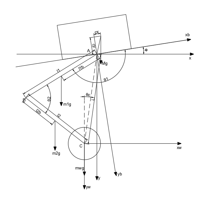
θ\theta 补偿实际就是通过为目标 θ\theta 添加一个前馈,使整个机器人的重心位于轮子的正上方,否则机器人由于重力与地面的支持力不在同一直线上时,会出现一个倾覆力矩,从而影响机器人的平衡性,如图所示
1745220026362.png

首先分析在机器人坐标系中,可以得到机器人各个部分重心的位置

Zb=[cx−cy]Zl1=[l1bcos⁡θ1l1bsin⁡θ1]Zl2=[l1cos⁡θ1+l2bcos⁡(θ2+θ1−180°)l1sin⁡θ1+l2bsin⁡(θ2+θ1−180°)]Zw=[l1cos⁡θ1+l2cos⁡(θ2+θ1−180°)l1sin⁡θ1+l2sin⁡(θ2+θ1−180°)]Z_b=\begin{bmatrix}c_x\\-c_y\end{bmatrix}\\Z_{l_1}=\begin{bmatrix}l_{1b}\cos\theta_1\\l_{1b}\sin\theta_1\end{bmatrix}\\Z_{l_2}=\begin{bmatrix}l_1\cos\theta_1+l_{2b}\cos(\theta_2+\theta_1-180\degree)\\l_1\sin\theta_1+l_{2b}\sin(\theta_2+\theta_1-180\degree)\end{bmatrix}\\Z_w=\begin{bmatrix}l_1\cos\theta_1+l_2\cos(\theta_2+\theta_1-180\degree)\\l_1\sin\theta_1+l_2\sin(\theta_2+\theta_1-180\degree)\end{bmatrix}

将上述重心坐标转移到轮子坐标系 xw−ywx_w-y_w 中,得到

Zb=[cos⁡φsin⁡φ−sin⁡φcos⁡φ][cx−cy]+[Lsin⁡θc−Lcos⁡θc]Zl1=[cos⁡φsin⁡φ−sin⁡φcos⁡φ][l1bcos⁡θ1l1bsin⁡θ1]+[Lsin⁡θc−Lcos⁡θc]Zl2=[cos⁡φsin⁡φ−sin⁡φcos⁡φ][l1cos⁡θ1+l2bcos⁡(θ2+θ1−180°)l1sin⁡θ1+l2bsin⁡(θ2+θ1−180°)]+[Lsin⁡θc−Lcos⁡θc]Zw=0Z_b=\begin{bmatrix}\cos\varphi&\sin\varphi\\-\sin\varphi&\cos\varphi\end{bmatrix}\begin{bmatrix}c_x\\-c_y\end{bmatrix}+\begin{bmatrix}L\sin\theta_c\\-L\cos\theta_c\end{bmatrix}\\Z_{l_1}=\begin{bmatrix}\cos\varphi&\sin\varphi\\-\sin\varphi&\cos\varphi\end{bmatrix}\begin{bmatrix}l_{1b}\cos\theta_1\\l_{1b}\sin\theta_1\end{bmatrix}+\begin{bmatrix}L\sin\theta_c\\-L\cos\theta_c\end{bmatrix}\\Z_{l_2}=\begin{bmatrix}\cos\varphi&\sin\varphi\\-\sin\varphi&\cos\varphi\end{bmatrix}\begin{bmatrix}l_1\cos\theta_1+l_{2b}\cos(\theta_2+\theta_1-180\degree)\\l_1\sin\theta_1+l_{2b}\sin(\theta_2+\theta_1-180\degree)\end{bmatrix}+\begin{bmatrix}L\sin\theta_c\\-L\cos\theta_c\end{bmatrix}\\Z_w=0

假定此时的 θc\theta_c 正好满足要求,此时根据重心公式可以得到

MZbx+m1Zl1x+m2Zl2x=0MZ_{bx}+m_1Z_{l_1x}+m_2Z_{l_2x}=0

求解可以得到 θ\theta 的补偿角度

θc=−arcsin⁡(m1l1b+m2l1)cos⁡(φ−θ1)−m2l2bcos⁡(θ1+θ2−φ)+M(cxcos⁡φ−cysin⁡φ)L(M+m1+m2)\theta_c=-\arcsin\frac{(m_1l_{1b}+m_2l_1)\cos(\varphi-\theta_1)-m_2l_{2b}\cos(\theta_1+\theta_2-\varphi)+M(c_x\cos\varphi-c_y\sin\varphi)}{L(M+m_1+m_2)}

在使用时可以直接添加到当前状态中,即状态空间方程变为

X=[θ−θcθ˙xx˙φφ˙]X=\begin{bmatrix}\theta-\theta_c\\\dot{\theta}\\x\\\dot{x}\\\varphi\\\dot\varphi\end{bmatrix}